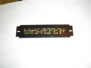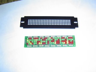


Here's the pic of what I got finished.
The surrounds need some buffing and I still need the Pic Flasher. Sorry the pics are alittle bright, But i wanted the detail to show.
After I got all the LEDS in the board, I had to find 2 that went bad during the soldering and replace them. The bad part was all I had to find them with was a 3 volt battery and a print of the pattern they were in.
Anyway all 108 leds work now.


3 comments:
OK..you sicken me withg your skills!!!
Looks GREAT! Mine are just leds that alternate and fibreoptics. They get the job done without having an electronics know-how!
Nice work!
Not really skills,
I just got lucky!!!
But I'm glad you liked the work.
Thank you!!
Hello, can you tell me how the electronic logic works
like what multiplexer/ic do you use
thx
Post a Comment