Thursday, February 28, 2008

Battery Box Work


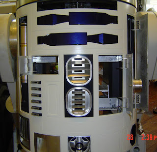
In these pics you can see the Main Batteries sitting on the plate. These are for the 24v foot motors and all I need now is to build something to keep them in place. You can see the Charge Port connector hanging down. This will be wired to the front small door for charging these batteries. I'm not sure yet how I will charge the 12v batteries. Maybe I'll hide another charge port for these. Since they will only be driving smaller acc. and lights, They should'nt need charging as much.

A&A Frame Mod


Here's the ideas I can up with to eliminate the rods in the belly area. After I hinged the Charge Port door and the door with the Restraining Bolt. I ran into a problem. The hinges were hitting the main body bolts that go from the top to the bottom of the frame. 1st I was going to move the rods, But the Arm Carriage depends on these rods for support and there's not enough room to move the rods. So, I used some aluminum to replace the support provided by the rods. The aluminum screws into the main frame and into the door sides and the frame rings. Now I have a clear body opening and the hinges have nothing to worry about.

Word Verify

I had to turn on this feature due to SPAMERS!!!!
I hate the idea that they will come on someone's blog and post bogus
links to garbage no one wants to see or read.
I have'nt done this in the past because it's kind of a pain for the reader
to post a comment and have to type in a special word.
Hopefully this will put a stop to this and building can continue.

Monday, February 25, 2008

Door Revised


I had to rehang this little door.
I normally use 3m foam tape for these doors,
But this little door needed a spacer for it to swing without hitting the edge. So I used a piece of aluminum between the hinge and the panel and this works fine now.

Sunday, February 24, 2008

Battery Box


I started building my 24v. battery box. I only have the bottom together so far, But soon I will have the top and lower lip ready.

It sits just above the center foot mount and will add more support for the frame. I made the box alittle bigger than I need for the batteries so it will be easy to add larger batteries later.

You might not be able to see it very well, But I got the rear electronic board mounted back in the frame. It's the shiney area behind the batt. mount.

Charge Port Door


I finally got this door hinged and this will be the port for charging R2.

As you can see in the pic, I have a small magnet that will keep the door closed. I will not be adding a servo to this door because it will only get used for charging. I have a 24v. battery charger that has a aluminum connector for charging. The connector will get dressed up to look like the connector in the movie. It won't be exact, But it will be close. I also plan to build the charge pack and hide a actual battery charger inside. The only problem will be that the movie shows very little of this charger and I'll have to guess at some of the details.

Pie Panel Setup


Here's my setup for the Pie Servo.

It's not fancy but it gets the job done.

I used a Hitec MG85 servo and a 4-40 linkage to the hinges. The hinges I added a small threaded rod from hinge to hinge and this gave me something to attach the rod too.

The only thing I want to change is the treaded rod, I want to used some smooth rod so the arm does'nt grab the threads as it moves. Also the rod in the hinges has to be free floating or it will bind up the hinges as the move. As you can see in the video, The servo has more than enough power to open/close the pie panel.

Saturday, February 23, 2008

Pie Panel Servo

Here's this weekend project.

I really don't know much about Servos, But I'm good at figuring things out that move.

I only have 1 Pie Panel moving and I need 3 more servos and linkage to get the other panels moving. Once I get all 4 Pies moving, I will have to make a decision on how to control all four.

Not being limited now with channels, But being limited by the Vex micro only having 6 usable servo ports. I may buy the Servo recorder from Servo City. This will allow me to use 1 channel on the Ebay 12 ch. remote. But the recorder will do the same movement of the pies each time I activate the recorder. More/Less, I can set the recorder to open pies 1-4, Then have it open 1 and 2, Then 3 and 4. This will give me a animation that will happen every time.

Sunday, February 17, 2008

Latest Work

Not much to show as far as pics, But I got some work done this weekend.
I finished wiring the dome lights and all I need now is the Slipring for power.
Since the electronics are now mounted to the dome itself, I will remove the plate
on the dome ring.
Things I will be working on next:
I need to install and wire all the servos for the dome Pie panels.
I need to get the dome side panel open and install the servo on that panel.
The front Holo needs a servo to get it moving.
As soon as 4D Electronics gets the video panel I need for the side of the dome,
I can get it installed and it will flash red until someone touches it and then the
pics will show.
That should pretty much complete the dome.

The Vex Remote I was working on failed :o(
The idea works, But I was getting some interference and it was causing the servo to jump.
If it was done as a PC board I think it would have worked fine.

I still have alot of work to get done to the rest of R2 and I will be hitting it hard from here
on out.

Thursday, February 14, 2008

Tuesday, February 12, 2008

More Arm Drive Pics


Here's the last pics I'll show of the drive because I'm going tho mount it for good.
All the parts used to build this drive is in the Vex Kit. It's very simple and could probly be improved. There's only 2 things I wish would have turned out alittle different.
I would have liked to stay with the larger gear in the drive, It held alittle better.
And I would have liked to use a Vex servo instead of a Vex motor, I'll have to be careful not to lift the arm to far. I may add a limit switch to the drive, But that will have to be later.
At any rate, This drive will work in just about any frame because the A&A is limited on space.

Monday, February 11, 2008

Almost There

Ok, After I had to rebuild the drive again.

I had to reduce the gearing due to space inside the frame, But it's mounted and after some fine tuning I'll have this project beat. I'll post some pics of the final drive soon.

Reduced Size

I started reducing the size of my arm drive and also found ways to make it stronger and easier to mount.
How I managed to make the arm turn with the shaft, I used more Vex parts.
They have some little mounts that come with the kit and I cut 1 end off and mount them inside the arm. This gives me something for the shaft to bite into and lift the arm.
As you can see in the pic, I tried not to scratch the arm but I did. This area is hidden by the swing mount and should'nt be a problem.


Well it Moves

In the video you can see it has more than enough power to lift the arm.

Now, I need to reduce the size of the drive and get it mounted into R2.

More to come.

Arm Drive

This is my Proto for the Arm drive.

Not much, But I think it may work.

Friday, February 08, 2008

CPU Arm Mounted

Although I have some adjusting to do to the mount because it's hitting my skin's,
I think I got it post fitted. The mount is bolted to the frame and as you can see it can be raised to the correct position. Now just to fine tune and get it moving.
Just a note: I have a threaded rod inside the arm and I hope to figure out a way to make the arm spin and extend about 1 inch once it's at full attention.


Thursday, February 07, 2008

CPU Update


I'm not giving up!!!!

Ethan, From the group had an idea sort of like this and I think it's going to work. I used a garage door opener front mount as a mounting bracket and drilled a pin hole through the arm.

This will give me a tight pivot point and since the cap is not part of the arm, I think I can make it work. This is just the start of a long process that hopefully will turn out O.K.

Wednesday, February 06, 2008

CPU Arm


The CPU Arm just seems to be too big for an A&A frame :0(
It's so tight that the hinges would have to be placed in certain areas and that's not good.
The whole idea of having the doors open was to use the openings for items to be placed.
I'm really dissapointed in this problem and not sure what to do about it. If I was going to build another R2 I could save the arm, But I don't have any plans to build another. So I may resale the arm to someone on the group. (CRAP!!!!!!)
It would just be a shame to let it just sit there and do nothing, I mean you could see it if the door opened but that's a expensive dead prop.

Saturday, February 02, 2008

Rewiring Dome


I moved a few things to the dome instead of the deck I had built on the dome ring.

The reason I did this, I'm working on the Periscope and noticed alot of things were getting to close to the area where the lift for the Periscope will be mounted. Also I want my dome to have easy access, Once I get all the wiring complete there will only be 3 main power lines to disconnect and the dome can be lifted off the body.

I know weight in the dome area is something to keep in mind, But I'm trying to keep it balanced around the dome. There's still many items to add to the dome and I figure by time I add servo's and all the extra goodies the dome will be pretty full.

Remote Update


I attached the little black box on the back of my remote for the extra crystal.
And believe it or not, The crystals fit like they were made for the box.
I did sand the edges of the crystal, So they would slide in/out very easy.
You can see inside where the original crystal would have fit and I cut the stem off of one crystal
to mount the wiring too.
All I need now is my 0n/off/on switch.
Once I get this complete, I'm going to give the whole remote a new paint job to match R2's colors.